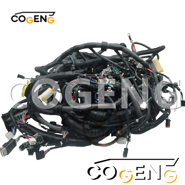
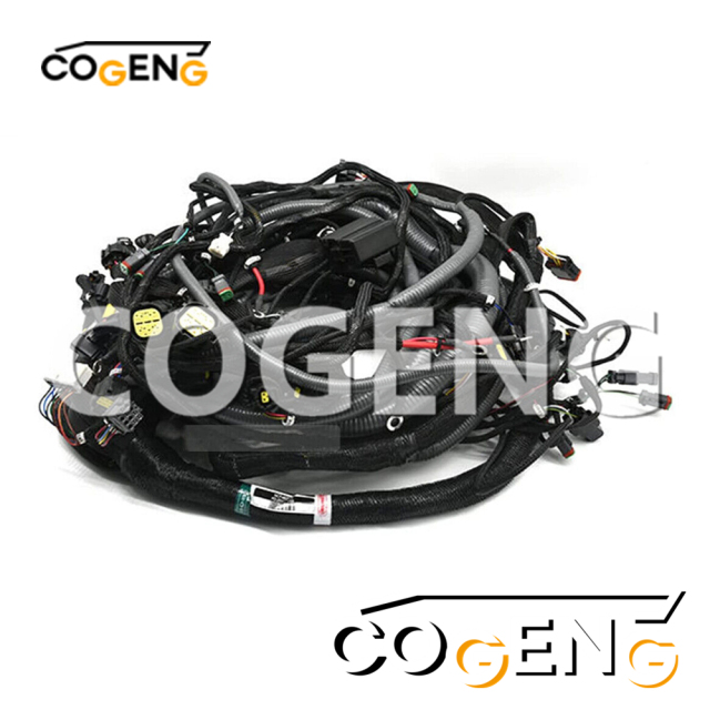
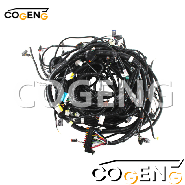
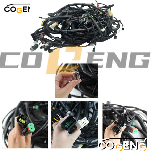
This extensive harness collection represents the entire electrical nervous system of your PC200-8E0, covering everything from engine management and hydraulic controls to operator interfaces, monitoring systems, and auxiliary functions. By replacing all major harnesses simultaneously, you eliminate the cumulative effects of aging wiring across multiple systems, ensuring balanced electrical characteristics and preventing future intermittent issues. COGENG's kit features coordinated construction with consistent wire quality, connector types, and protection levels across all five harnesses for optimal system integration and long-term reliability.
Key Features & Benefits:
Complete System Renewal: Five-harness kit provides comprehensive electrical system replacement
Coordinated Performance: Matched harness set ensures consistent electrical characteristics across all systems
Enhanced Durability: Uniform high-temperature protection and abrasion resistance across all harnesses
Advanced Environmental Sealing: IP67-rated connectors throughout with improved corrosion resistance
Future-Proof Reliability: Addresses potential failure points before they cause operational downtime
| COGENG Part Number | Replaces OEM Number | Primary Application | Key Features |
|---|---|---|---|
| CG-WH-KOM-D1820 | 20Y-06-D1820 | Main Chassis Harness | Power distribution, main controllers |
| CG-WH-KOM-D1821 | 20Y-06-D1821 | Engine Control Harness | ECM, sensors, fuel system |
| CG-WH-KOM-D1822 | 20Y-06-D1822 | Operator Station Harness | Controls, displays, monitoring |
| CG-WH-KOM-D1823 | 20Y-06-D1823 | Hydraulic Control Harness | Solenoids, pressure sensors |
| CG-WH-KOM-D1824 | 20Y-06-D1824 | Auxiliary Systems Harness | Lighting, accessories, options |

| NO | Number | Name | Qty |
| 1 | 20Y-06-D1820 | WIRING HARNESS | 1 |
| 20Y-06-D1821 | WIRING HARNESS | 1 | |
| 20Y-06-D1822 | WIRING HARNESS | 1 | |
| 20Y-06-D1823 | WIRING HARNESS | 1 | |
| 20Y-06-D1824 | WIRING HARNESS | 1 | |
| 2 | 08020-20000 | • DIODE | 2 |
| 3 | 08041-00500 | • FUSE, 5AMP. | 3 |
| 4 | 08041-01000 | • FUSE, 10AMP. | 12 |
| 5 | 08041-02000 | • FUSE, 20AMP. | 3 |
| 6 | 08041-03000 | • FUSE, 30AMP. | 2 |
| 7 | 19M-06-31720 | • RESISTOR | 1 |
| 8 | 20Y-06-31660 | • FUSIBLE LINK, 30AMP. | 1 |
| 9 | 22U-06-11270 | • FUSIBLE LINK, 65AMP. | 1 |
| 10 | HM6400-0012 | • F-CONNECTOR, BLACK | 2 |
| HM6409-0071 | • M-CONNECTOR, BLACK | 2 | |
| 11 | HM6400-0013 | • F-CONNECTOR, GREEN | 2 |
| HM6409-0072 | • M-CONNECTOR, GREEN | 2 | |
| 12 | HM6440-0129 | • F-CONNECTOR, PINK | 1 |
| HM6440-0128 | • M-CONNECTOR, PINK | 1 | |
| 13 | HM6400-0016 | • F-CONNECTOR, ORANGE | 1 |
| HM6409-0075 | • M-CONNECTOR, ORANGE | 1 | |
| 14 | 20Y-62-22790 | • BAND, RED | 2 |
| 15 | 20Y-62-22810 | • BAND, YELLOW | 1 |
| 16 | 20Y-62-22830 | • BAND, WHITE | 2 |
| 17 | 20Y-06-D1790 | CABLE | 1 |
| 18 | 08038-00035 | CAP, TERMINAL | 1 |
| 19 | 20Y-06-22872 | CABLE | 1 |
| 20 | 08038-06031 | CAP | 1 |
| 21 | 08088-30000 | SWITCH, BATTERY RELAY | 1 |
| 22 | 08038-00519 | CAP | 2 |
| 23 | 08038-06031 | CAP | 1 |
| 24 | 600-815-2170 | SWITCH, HEATER | 1 |
| 25 | 08038-00519 | CAP | 2 |
| 26 | 600-815-8941 | RELAY | 1 |
| 27 | 20Y-06-D1660 | CABLE | 1 |

| Part No. | Harness Name | Main Connectors / Functions | Primary Routing Location |
|---|---|---|---|
| 20Y‑06‑D1820 | Engine harness (SAA4D107E‑1) | Engine ECM, crankshaft position sensor, camshaft position sensor, rail pressure sensor, fuel injectors (Zexel/Denso), EGR valve, turbocharger boost sensor, water in fuel sensor, oil pressure switch | On engine – left side (from cab view), along cylinder head and injection pump side |
| 20Y‑06‑D1821 | Main chassis harness (front) | Starter relay, alternator (B terminal), battery positive cable junction, main fuse box (F01), glow relay, AC condenser fan, horn, headlights (both), working lights (boom & cab) | Front frame – from battery box to radiator area, along right chassis rail |
| 20Y‑06‑D1822 | Main chassis harness (rear) | Battery negative (ground) to engine block, swing motor brake solenoid, swing encoder, hydraulic lock solenoid, tail lights, beeper, rear working light, fuel level sender, hydraulic oil temperature sender | Rear frame – from battery box to swing circle, swing motor, and rear counterweight area |
| 20Y‑06‑D1823 | Cab harness (upper) | Monitor panel (C‑3), right joystick (PPC lock, horn, one‑touch idle), left joystick (travel alarm cancel, auto idle), key switch (ACC, ON, ST), HVAC control panel, wiper motor, radio, cigarette lighter, floor heater, cab lamp, door switch | Inside cab – behind right console, under floor mat (to key switch), up to monitor, across roof for wiper/cab light |
| 20Y‑06‑D1824 | Attachment / arm & boom harness | Bucket angle sensor (if equipped), arm angle sensor, boom angle sensor (optional), attachment control valve (hammer/rotator), quick coupler solenoid, boom working light (mid/tip) | Outside – along boom foot to arm tip, protected in split conduit, secured to hydraulic hoses |
✅ Note: PC200‑8E0 uses the SAA4D107E‑1 engine (Tier 3 / Stage IIIA). These harnesses are not interchangeable with PC200‑8 (non‑E0) which has an older engine control system.
This order follows logical assembly and avoids re‑work:
Disconnect battery negative terminal
Remove floor mats and right console cover (for cab harness access)
Open engine hood and remove top cover
Lay harness along engine left side (injector side)
Connect:
Engine ECM (mounted on left engine rail)
All sensors (cam, crank, rail pressure, boost, oil pressure, water in fuel)
Injectors (cylinder order 1→2→3→4 from fan end)
EGR valve and EGR position sensor
Secure with factory clips or new zip ties (heat‑resistant type)
Start from battery box (positive junction)
Route along right chassis rail toward radiator
Connect: starter (B terminal + signal wire), alternator (B and IG), fuse box F01, glow relay, horns, headlights
Also connects to AC condenser fan (if equipped)
From battery negative terminal, route to engine block ground point (clean contact)
Swing section: connect swing motor brake solenoid & encoder (under swing circle cover)
Rear section: tail lights, beeper (buzzer), rear working light, fuel sender, hydraulic oil temp sender
⚠️ Critical: D1821 and D1822 join at the rotary union junction block under cab. Confirm all pins match before closing.
Remove right console panel (ECM mounting area)
Feed harness from engine bay through firewall grommet into cab
Connect: monitor (rear of monitor), key switch (ACC/ON/ST), joystick connectors (under right armrest)
HVAC control, wiper motor, cab lamp, door switch
Ground to cab chassis (under right console)
Secure to existing hydraulic hose bundle (outside boom)
Route from main chassis connection point (near swing joint) → boom foot → arm tip
Connect: boom light (mid/tip), optional angle sensors, quick coupler solenoid, attachment valve
Use conduit or spiral wrap to prevent abrasion
Inspect all connectors for corrosion and proper seating
Secure all harnesses away from heat sources (turbo, EGR pipe, exhaust manifold)
Reconnect battery → key ON (engine OFF) → check monitor for error codes
Clear any CAN bus or open circuit codes via Komatsu Diagnostic Tool (if available)
| Symptom | Likely Cause |
|---|---|
| Engine cranks but no start | D1820 injector harness pins miswired (cylinder order wrong) |
| No swing brake release | D1822 swing motor brake solenoid circuit open (check ground) |
| Monitor blank / no power | D1823 pin 15 (BAT+) or pin 14 (GND) at monitor connector C‑3 missing |
| Headlights or working lights dead | D1821 front chassis harness – fuse box F01 relay or ground point near battery |
| Attachment hydraulic not responding | D1824 attachment harness – quick coupler solenoid polarity reversed |
Because I cannot embed copyrighted PDFs, use these resources to find the actual exploded view with connector locations:
Komatsu Service Manual (SEN03997-01) – Electrical system section, wiring diagram, and harness routing diagrams for PC200‑8E0.
Komatsu Parts Catalog – Enter model → search 20Y‑06‑D1820 → view "Harness" group illustration.
COGENG technical support (email: tech@cogeng.co.kr) – Request installation diagram for set 20Y‑06‑D1820~D1824.
Aftermarket parts sites (e.g., AVSpares, Lifting365, TractorZone) – Search each part number individually; sometimes they provide PDF breakdowns.
Contact COGENG
📞 Phone: +86-185-2913-1515 🌐 Instagram
📧 Email: hugo@cogeng.net 🌐 Facebook:Excavator Parts Selection and Replacement Community
💬 WhatsApp +86-185-2913-1515 Facebook: Excavator Wiring Harness
💬 WeChat: +86-185-7865-1106 Facebook: Excavator Wire Harness
🌐 Website: cogeng.net Facebook: Excavator SolenoidValve
#ExcavatorWiringHarness #ExcavatorThrottleMotor #ExcavatorSolenoidValve #ExcavatorSealKit